System topology diagram
The primary use case for managing the Next-Generation Firewall (NGFW) capabilities of Catalyst SD-WAN through Security Cloud Control Firewall Management is to streamline and centralize security management across Cisco's security products.
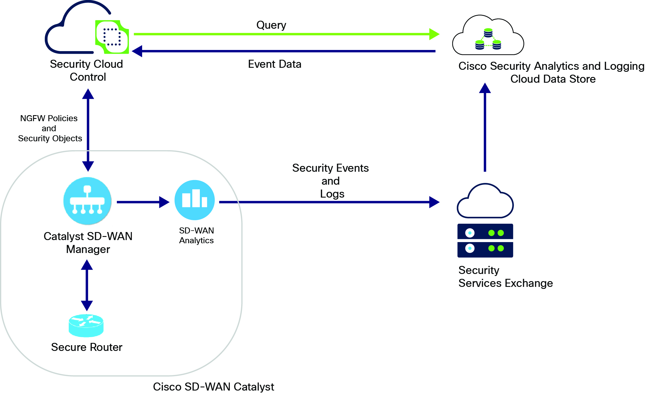
The topology diagram illustrates the integration of Catalyst SD-WAN with Security Cloud Control Firewall Management and other cloud services. The diagram shows the flow of information and interactions between various components.
Note | The Cisco Catalyst 8000 and Secure 8000 devices are collectively referred to as the 'Secure Router' hereafter. |
-
Security Cloud Control: A central point for security policy enforcement and event correlation. It reads Next-Generation Firewall (NGFW) policies and security objects from the onboarded Catalyst SD-WAN Manager and allows customers to modify these NGFW configurations. It also sends queries to Cisco Security Analytics and Logging cloud data store for events.
-
Cisco Catalyst SD-WAN consists of:
-
Catalyst SD-WAN Manager: Manages the SD-WAN fabric and displays NGFW policies and security objects in Security Cloud Control when onboarded to it. Catalyst SD-WAN Manager sends the event data received from Secure Router to SD-WAN Analytics.
-
SD-WAN Analytics: Provides analytics data to the Security Services Exchange.
-
Secure Router: The SD-WAN edge device.
-
-
Cisco Security Analytics and Logging Cloud Data Store: A cloud-based repository for security analytics and logging data. It receives security events and logs from Security Services Exchange, which obtains the analytics data from SD-WAN Analytics engine.
-
Security Services Exchange: A cloud-based platform designed to facilitate the integration, communication, and management of various Cisco security services. It sends security events and logs received from the SD-WAN environment and forwards them to the Cisco Security Analytics and Logging Cloud data store.